
When a Gravity Wall Isn’t Enough: Geogrid, Surcharge Loads, and Retaining Wall Failure Points

Stacking segmental retaining wall (SRW) units looks deceptively simple. Dig a trench, level a crushed aggregate base, set your dry-cast blocks, backfill, and repeat.
For a 2-foot landscape planter, that approach works fine. The self-weight of the concrete units and the setback lip are more than enough to hold back the soil behind them. This is the definition of a gravity wall… a structure that relies entirely on its own mass to resist the lateral earth pressure of the retained soil.
However, once a wall gains height or faces external site pressures, relying solely on block weight is a recipe for catastrophic blowout. Understanding where gravity walls reach their structural limits (and how Mechanically Stabilized Earth (MSE) systems take over) is the difference between an installation that lasts 50 years and one that fails after the first heavy spring thaw.
1. The “4-Foot Rule” (It’s Shorter Than You Think)
In most municipal jurisdictions following the International Building Code (IBC) or International Residential Code (IRC), any retaining wall over 4 feet tall requires certified engineering stamps and permits.
What trips up many contractors and property owners is how that height is measured:
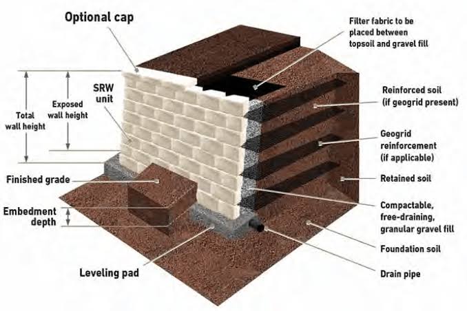
- Total Height vs. Exposed Height: The 4-foot threshold is measured from the top of the leveled footing or leveling pad to the top of the wall cap, not just what is visible above the finished grade.
- Embedment Depth: Industry standard requires burying at least one full block (or 1 inch of buried block for every 1 foot of wall height) for baseline toe stability. A wall showing 3.5 feet of block above grade often has 6 to 10 inches buried below grade, pushing the total structural height past the 4-foot mark.
At this height, internal soil shear planes shift. The triangular wedge of earth pressing against the backside of the wall exceeds what concrete friction and setback pins can retain on their own.
2. Surcharge Loads: The Silent Multipliers
A wall doesn’t need to reach four feet to fail if it is subjected to a surcharge load, an external vertical load applied to the soil surface behind or above the wall.
Surcharge forces travel downward and radiate laterally through the soil, multiplying the active pressure trying to overturn or slide the wall:
- Sloped Backfill: Flat backfill exerts standard lateral pressure. An upward back-slope behind the wall (such as a 3:1 or 2:1 hill) dramatically enlarges the active soil failure wedge, turning a 3-foot wall into the structural equivalent of a 5- or 6-foot wall.
- Vehicular Traffic: Driveways, parking stalls, or access lanes located within a distance equal to the height of the wall require an engineered live-load surcharge allowance (typically a minimum of 250 lbs/sq. ft.).
- Fences and Guardrails: Post footings cored into the top course or placed directly behind the wall act as levers. High wind loads against a privacy fence transfer intense lateral torque directly onto the top courses.
- Adjacent Structures: Inground swimming pools, patio footings, building foundations, or even large boulder outcroppings inside the 45-degree influence line of the wall face transfer immense localized point loads into the retained backfill.
3. Geogrid Mechanics: Turning Dirt into a Structural Mass
When a gravity wall hits its limit, the solution isn’t simply heavier block. It is soil reinforcement using geogrid.
Geogrid changes the physics of the entire installation. Instead of the block face acting as a dam holding back millions of pounds of wet earth, the geogrid layers interlock with compacted aggregate to create a unified, composite gravity block called Mechanically Stabilized Earth (MSE). The block face merely acts as a facade to prevent surface erosion; the reinforced soil mass behind it is what actually holds back the hillside.
Key rules for proper geogrid performance:
- Roll Direction Matters: Uniaxial geogrids have high tensile strength in one primary direction (the roll direction). Laying a uniaxial grid parallel to the wall face provides virtually zero structural restraint. It must be rolled out perpendicular to the wall face.
- Embedment Length: As a general baseline, geogrid length should extend back into the reinforced zone at least 60% of the total wall height ($0.6 \times H$), and rarely less than 4 feet deep. Surcharges or steep back-slopes will push this requirement deeper.
- Tension and Compaction: Lay the grid flat, pull it taut to eliminate slack, and stake the back edge before placing backfill.
- Never Run Heavy Equipment Directly on Grid: Always keep at least 6 to 8 inches of aggregate between equipment tracks and the geogrid. Compact fill in loose lifts no thicker than 8 inches, running plate compactors parallel to the wall face from front to back.
4. Hydrostatic Pressure: The #1 Killer of Retaining Walls
Most retaining wall failures are not caused by soil weight, they are caused by water.
Dry soil exerts roughly 30 to 40 lbs per cubic foot of active lateral pressure. Water weighs 62.4 lbs per cubic foot. When water backs up behind an un-drained wall, the combined hydrostatic load easily doubles or triples the pressure on the structure while lubricating the soil particles, drastically reducing internal friction.
To prevent blowout and catastrophic wall lean:
- The Drainage Column: Place a minimum of 12 inches of clean, angular open-graded aggregate (such as AASHTO #57 crushed stone / 3/4″ clean) directly behind the block column. Avoid rounded pea gravel, which lacks the interlock needed for structural stability.
- Perforated Drain Pipe: Run a 4-inch perforated collector pipe at the lowest practical point behind the wall, sloped to drain away by gravity. Never wrap the perforated pipe directly in “filter sock” in fine soils—wrap the entire drainage stone column in a non-woven geotextile fabric to prevent native silt from blinding the drainage zone.
- Daylighting to Positive Outflow: A perforated pipe that terminates in dead dirt is just an underground reservoir. Always daylight the drainage pipe through the wall face, around the ends of the wall, or plumb it directly into an active storm drainage system.
- Surface Swales and Clay Caps: Cap the top 6 to 12 inches of the backfill with a low-permeability cohesive soil (or vegetative cap) to direct surface runoff toward catch basins or swales rather than allowing it to saturate the aggregate backfill zone.
Structural Integrity Starts Below the Surface
A segmental retaining wall is only as strong as the reinforced mass behind its front face. Before breaking ground on any retaining project that exceeds three feet or carries an overhead load, factor in the entire engineering package: base embedment, drainage stone volume, proper geogrid tensile ratings, and compaction protocol.